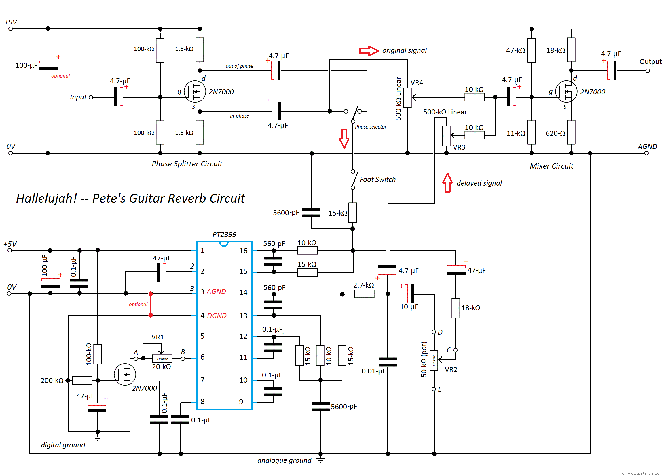
I added a second channel, so reverb - echo could be fed to stereo recorder. The circuits helped, as an output IC would drive a cable, things like that. Many musicians like effects, a bit dialed back. The pedal came with schematics: most OP AMP circuit stages are simple, with AC gain of X5 etc. That gives a 40 millisecond retort, barely audiably delayed, but only one (one loud echo). So for a 1950 s slap-back sound, you would turn down the REGEN, and turn up MIX. For sound effect, only the first two knobs are used (having a 'Program Regen.' knob, for echo repeats (persistence). So the range of that first knob is about 1 to 8. On the other end, of speed, a fastest clock setting of 48 khz, for example, will cause a 40 milli-second audio delay. It had a RIDICULOUSly low clock, at 6 khz ! Or even lower, maybe, as the delay put through the IC (2 k Bucket Brigade chip) turns out to delay any audio by about 333 mili-seconds. I owned a DOD brand Reverb Pedal, circa 1985. I bought my pedal at local pawn shop! Cheap! Thanks Oh, and if you do go with the bucket brigade IC route, that IC needs a CLOCK pulse supplied (I think that's around 30 khz) There's plenty to be learned there, nice thread, please continue this, and any questions as you go. So, best place to re-start, maybe try some of the blogs around that 4 dollar kit, and keep checking in here with more specific questions. Actually, 'cheating' is asking questions like "does anyone have a spice model so you can just, blindly hook up a bunch of components when you have no clue. It's the mixed signals that goes to the delay IC, with the fed back (delayed sound) signal going thru a potentiometer, for dialling in how much effect / clean. Just a short study, and you could rapidly understand the OP AMP use, in this context. Then: Can you diagram an audio mixing stage, taking your buffered guitar input, mixing with feedback line, from your output buffer (that drives the actual output jack)? Without those two simple methods, using the LM1458 for each circuit, you are lost. I mean, here is a test: Can you write a diagram for a basic, 2X ac amplifier, and discuss how it works ? That would be your input buffer.

I had bought a cheap guitar reverb pedal, that had used the IC LM1458, and try various guitar boards. The reference to the 4 dollar kit board, with PT2999 (yeah, I got that wrong too), looks like 'learning opportunity' to me. I agree with jonovid, get an existing project board, as that will be documented. So try to find an analog bucket-brigade design you can look at. This is complicated stuff - well-worth it if you are developing a high-volume commercial product, but probably more than you want to take on as a hobbyist. You will need some type of user interface to let you actually use this thing. You will want to have varying amounts, durations, and types of echo, and this will be done under firmware control. The controller then needs to read data from the buffer - probably from several locations and then scale and combine the data, writing the result out to the DAC.

You will then need a controller or FPGA to trigger and read data from the ADC at a fast rate (96 HKz?), then write it into a memory buffer. The analog/digital/analog method probably needs a higher-resolution ADC/DAC that that AD7910 - that is 10-12 bits and you probably want at least 16-24 bits for acceptable distortion. Pins 7 and 8 usually around 0.If you can find the bucket-brigade chips (as msat mentions), that is probably the easiest way for you to go. If you look at Merlins datasheet you'll see internally the 2 x 5K6 resistors forming a voltage divider across pins 1, 2 and 3 to give us the VREF voltage at thier junction which biases the internal op amps you can see with the VREF flags going to the + inputs, so that tells you all the internal op amp input and output pins should be at VREF voltage 2.5v ish (or whatever pin 2s voltage is) Pin 2 half of pin 1s voltage or VREF (voltage reference) The PT2399 is a single chip echo processor IC utilizing CMOS technology. Pin 1 should be 5v ish as long as it's more than 4.5v the minimum required supply voltage it's fine Pin 14 looks high it should I think be at VREF voltage: Yes common probe to any ground point and positive to PT2399 pins, the 7805 metal bit is attached to the ground middle pin so that's OK as a ground point "Understanding How Transistors Work" - Stompbox StudiesĪmplified Parts - Pedal Layouts & Build Guides "Everything You Need to Build a DIY Guitar Pedal" - Pedal Haven "So you’re starting out - A guide to what you’ll need to build pedals." This is an open community for the do-it-yourself pedal builders of reddit! Please use this subreddit to share knowledge, give/receive help, and show off your custom builds! Looking for troubleshooting help? Please read this first!


 0 kommentar(er)
